
Ham stackexchange
Nyhetsflöde med senaste 30 inläggen från forumet
-
In programming an Icom IC-F6011, what settings are necessary for CTCSS Decoded squelch?
I'm trying to configure an Icom IC-F6011 for one channel, with a 218.1Hz decode, with microphone hanger Off or On ground, using CS-F3020/F5010/F5020 software Ver. 3.4.
I have the C.Tone, RX set to 218.1Hz. I have the Common, Key & Display, Hanger Action, Off Hook(Monitor) set to ON. Verified mic knob connection to plug.
I have Googled this over and over with very similar results(I realize often erroneous), but little other relevant specific search results return.
I have tried(based on web searches):
[Done] Open the Channel Spreadsheet: Go to Memory CH -> Zone where your frequencies are configured. Verify the Sub-audible Tone: Enter CTCSS frequency (218.1 Hz) into the C-Tone RX column.
[Can't find or non-existent?] Change the Log-In/Squelch Mode: Look for the Squelch Mode or Log-In column (often located further down the row or right next to the tone selection). Change this setting from Carrier to CTCSS/DCS. This forces the radio to remain muted until it detects the explicit code.
[Not found] Link the Operating Signaling: Look for the RX Code CH or Signaling option on that channel line. Ensure it is mapped to Tone or LMR/PMR tone squelch so the microprocessor blocks un-toned traffic. The Model is set to LMR.
Step 2 would probably solve this, but not found. Under Common, Key & Display, Hanger Action, I have the Off Hook Monitor set to OFF.
So I have carrier squelch regardless of mic hanger state. What steps am I missing?
-
Does MeshCore support Meshtastic's Smart Filter / Location Broadcast Interval / selective location sharing?
I have a custom device that I tried with Meshtastic. Among its features were Smart Filter, Location Broadcast Interval, and also message and location encryption.
Because of MeshCore's better features, I switched to it and ran several tests, including sending location. However, I ran into a problem: it broadcasts the location publicly, meaning that if there's another device with the same settings, it can easily see my location. I then went into the settings and disabled "Share Position in Advert," and under the Telemetry section I selected "From Specific Contacts." Then, from the details of the specific node I want to be able to see my location, I went into Permissions and enabled "Allow" on the options, so now that node can see my telemetry data. However, I haven't found this to actually work in practice.
Does MeshCore have the Meshtastic features I mentioned above, and if so, what's the method to implement them?
-
1928-1930 HF radiotelephone connections between the UK and the US - did GBU switch its highest frequency?
I am researching the history of the shortwave curtain antennas in use at the AT&T shortwave transmitting station at Lawrenceville, NJ (the "Pole Farm") in the period 1929-1930, and have a question about its opposite number at Rugby, where GPO, the predecessor of BT, had its transmitters. The three call signs at Lawrenceville were WND, WMI, and WNC, and their opposite numbers were GBS, GBU, and GBW, respectively. An antenna layout diagram for the AT&T receivers at Netcong, NJ (in a 1930 BSTJ paper) seem to indicate that GBU at some point used the wavelengths 16.0 m, 24.4 m, and 30.1 m, but DX reports published in 1930 report GBU using 16.11, 24.4 and 30.15 meters. So the question is, did GBU switch its highest frequency antenna at some point near the end of 1929?
I am aware of a book "The History of Rugby Radio Station" by Malcolm Hancock, but have not yet received my copy. If anybody knows of someone who might know the answer, or who knows how to contact Mr Hancock, I'd really appreciate hearing from them.
Thanks in advance.
-
FM Tube Study Radio Revision Feedback
I've made a couple questions on this endeavor so far. I'm somewhat new to electronics and love tube equipment, so I set out to design and build a tube FM radio as a study project. After studying some FM only tube radios I've come up with this revised schematic draft. I didn't want to just copy a radio so I made it my own, but as a result of that and my lack of experience I would like feedback, circuit change suggestions, value change suggestions, etc. Some components don't have labeled values, and this is because I need to find the transformers for purchase first, then I'll get capacitors for the right frequency response. I decided on a tickler coil local oscillator with a separate mixer tube, and the ratio detector closely resembles the design from the audio portion of a television set I have. The power supply has already been designed and I'm confident in it.

-
FM Radio Design For an Electronics Beginner
My goal is to build a vacuum tube FM radio from scratch. I'm mostly a beginner but I know some basics of vacuum tube circuits. I also know the general blocking out I need. RF amp -> Local Osc. + Mixer -> 2 or more IF -> ratio detector -> audio preamp -> AF power amp. I also know how to draw load lines. My question, basically, is what do I need to know about circuit design? What RF and AF circuit principles should I know, and what are some good resources for the info necessary?
-
FM Radio Design Feedback, By Newbie
I'm new to electronics in general, but I love working on tube stuff so I'm designing and building an FM radio from scratch as a project. I've come up with a draft for the schematic and would like feedback on the circuit design and component values. The IF cans and ratio detector transformer will be bought with standard values, 10.7 MC IF. I have a power supply design that for sure works, supplying around 385VDC B+ and 6.3VAC for the filaments. I didn't really find a good program for drawing tube schematics so it's drawn by hand on a piece of paper, sorry in advance. Thanks!

-
How Does This Particular Ratio Detector Work?
(below text is a schematic that is referenced heavily)
I'm trying to understand the ratio detector circuit for the audio in the SAMS schematic for the Admiral 20x1 1949 television chassis. The reason I'm stuck is because it's not the typical detector circuit you would find in a textbook, namely, what I've labeled as "Section A" is different, as well as the connection back to the tertiary winding.
In a basic ratio detector, labels e1 and e2 are 180 degrees out of phase, and each 90 degrees out of phase with the secondary current. At resonance, the secondary current is in phase with the secondary voltage (ep), and this current swings phase back and forth around ep's phase as the frequency increases and decreases around the center frequency.
This tilts the phasor describing e1 closer to, and the phasor describing e2 further from ep, and vice-versa. This creates a difference in amplitude between ep+e1 and ep+e2 at frequencies above and below the center frequency.
The difference between ep+e1 and ep+e2 is the output audio signal. Usually, the difference in voltage sums would lead to different currents through the two diodes which would charge two capacitors in the same configuration as R41 and R40, with a load resistor between the center tap of those capacitors and ground. The difference in charge on those caps would form a potential difference between their center tap and the evenly split resistor divider (R41 + R40), center tapped at ground, giving the required potential across the load resistor between the two center taps.
Here's what I assume is going on here, but I would like someone more knowledgeable to chime in: C4 acts as an AC short, allowing current to flow equally to the tertiary from both diodes. When operating in resonance, ep+e1=ep+e2 and the currents through both diodes are equal. This means all the current flows through the loop charging C4 and creating a voltage divider across R40 and R41, leaving no current flowing through the tertiary.
Therefore, there is no voltage drop across R42 and the output is zero. When the frequency deviates, the current through the diodes becomes unbalanced, and the difference is made up for by a current through R42, creating a voltage drop that becomes the output.
Specifically, the output is the center tap of the voltage divider composed of R42 and resistors R40 and R41 in parallel, as that is how the circuit appears from an AC perspective.
This is what I've come up with, but please correct me if I'm wrong, I would like to fully understand the operation of this circuit.
(Side note, if anyone has recommendations for books on vacuum tube tv/radio receiver circuitry design and operation, that would be greatly appreciated.)
Schematic taken from https://www.earlytelevision.org/pdf/admiral_20x1_sams_100-1.pdf

-
Adaptive threshold for weak pulse detection in non-stationary noise and interference
In my experiments with receiving very weak signals, I need to detect a pulse with an extremely low signal-to-noise ratio (well below 0 dB) in the presence of a non-stationary, time-varying interferer and the combined noise of the receiving system (thermal noise, ADC quantization noise, and phase noise). Currently, for single-channel hardware, I am using a train of pulses (for example, 128 pulses) and applying coherent integration to improve the signal-to-noise ratio before detection. Detection is performed in the time domain (or after matched filtering). I have encountered the problem of choosing an adaptive detection threshold that would take into account the fact that the noise and interference are non-stationary — their level and statistical characteristics change from one pulse train to the next. My specific questions are: 1. What are the most robust and practical methods for estimating the noise floor in real time under non-stationary noise conditions, in order to set the detection threshold for a given probability of false alarm (Pfa)? 2. Are there adaptive thresholding algorithms that work well with coherent integration, without assuming white or stationary noise? 3. What is the best way to combine decisions (or statistics) from multiple integrated pulse trains to improve detection, especially when the interference is not constant? (This question will become particularly relevant when transitioning to a 16-channel DAA.) I am interested in practical advice and references to field-tested algorithms, rather than general theoretical discussions.------------- Instead of my estimates of received signal characteristics and track noise perhaps forum participants may be interested in recordings of real signals. If anyone is interested, email me and I can send a *.dat file and some numerical results of software or screenshots of graphs. I can also send a Matlab program to read my *.dat files.
-
Less Sensitive RTL-SDR Blog V4 at UHF/VHF Frequencies
recently I have been troubleshooting a faulty RTL SDR V4 dongle, I noticed it is much less sensitive (in the UHF/VHF bands) than another dongle of the exact same type.
Sensitivity checked via SDR software on multiple computers...
Software tested with SDRangel, SDR++, SDRSharp etc. all the same results it's definitely a dongle fault.
I assume it may be a IC difference or faulty filtering and would like to know if anyone has experienced similar issues and know what the cause may be?
I elaborated a bit via this question but seemed to have sent it to the EE stack instead of Ham stack...
I suspect it could just be some impedance mismatching but the pf and nH values are so small it's not possible for me to do any proper tests with equipment available to me.
I would just buy a new one and call it a day but I have a curious itch as to the cause of this less sensitivity.
I have included 2x close up photos of the filtering area below:
PHOTO 1

PHOTO 2

None the less, I still stand by my troubleshooting question. Has anyone had the same or similar issue with the RTL V4 blog and know of the cause and potential solution?
Any help or advice would be greatly appreciated thanks.
-
How does an antenna tuner work to remove the mismatch at the antenna's feedpoint?
There is a lot of confusing information out there. Some say tuners only mask the mismatch and do not remove it. Some others say that the reflected power coming back from the antenna continues to exist and that the tuner reflects it back up to the antenna.
What is the true mechanism of how an antenna tuner works, and how does it bring a match at the antenna's feedpoint?
-
Copying unfamiliar words above 20 wpm
I can copy about 15 wpm, and I'm trying to get faster than 20 wpm. I've been stuck for a while.
I understand the concept of hearing common words and fragments ("the" "and" "ing" etc.) as a single unit, and indeed I can pick those out at 25-30 wpm. With practice, I expect I will get to recognize more and more of these. But for those who are comfortable at higher speeds, how do you deal with completely unfamiliar words (e.g., place names, or unusual vocabulary)?
I have experimented with turning each heard letter into a visual representation in my mind, and "reading" what I visualize (R A D I O); I have experimented with saying each letter in my mind as it comes and deciding what it spells (arr aey dee eye owe) I have experimented with mentally "sounding out" groups of letters as they come, and then recognizing what the word is by the end (rad radi radio). They all sort of work, but I don't know what is the best approach.
Are any of these methods familiar to those who are comfortable at > 20 wpm, or is there another practice that's better altogether?
-
How do I make an antenna for a portable QRP Labs QMX/QCX?
I am interested in buying a QRP Labs QMX or QCX transceiver. My goal is to have a portable transceiver that I can take on hikes with me to work CW (and optionally, voice) on my trips. Here are a few questions:
- It seems that the kits do not come with an antenna, so how do I make one? What is the best wire to use, what length should it be, and do I need to purchase a connector to attach it to the transceiver?
- What kind of battery could I use to power this away from home?
- Where can I get a small CW paddle?
73 DE OH2UWU
-
Mobile Helical Antenna frequency: rule of thumb given shortness?
I have a collection of helical mobile whip antennas obtained from club Auctions .How would I find out the approx operating freq ? These are shorter than quarter wave .Is there a rule of thumb about how much shorter the helical is ?
-
What kind of hexagonal antenna is this?

On the left there apparently is perhaps some poorly maintained civil defense sirens, or maybe just lights, and a lightning rod. But what is that antenna(?) on the right? For all I know it might be a wind powered popcorn maker. Seen in central Taiwan.
Rear view:

I went there but there's no doorman to ask, just shops who don't know anything about it. I didn't wait around to hassle anybody coming in or out, nor did I sneak in behind them, as that isn't welcome:

Even if it was one day some spy operation, nowadays they've got electrical problems:

As a matter of fact the place is an air raid shelter that can hold 240 people!

Across the street there's the community patrol office, complete with VHF omnidirectional "木瓜天線" antenna. A massive joss paper furnace is at the left:

-
How do I get the Host Metrics from the Meshtastic CLI?
In the Meshtastic Android app, on the Details page of each node, there is a Host Metrics button which when clicked displays information like this:

How can I get that information from the Meshtastic command line interface?
-
Finding an antenna-theory Master's Thesis from 1965
I´m urgently searching for this Master´s Thesis:
Lain, W. Y.: Higher order normal modes on a helical dipole antenna; Master´s Thesis, University of Illinois, Urbana, 1965
Does anyone have access to this paper? If so, is it possible to get a copy (PDF scan or microfiche)? Please let me know if there are any costs associated with your efforts.
Thanks in advance and 73, Tom Koelpin, DK1IS
-
G6ALU 20W PA for Radioberry
I had my first ham license when I was 18 and have an engineering degree but then left it in the background for the next few decades and my neuron connections deteriorated. I want to get back into the hobby, so I got my ham license a few months ago and bought a Radioberry. I also want to get back into building circuits and was looking at the G6ALU 20w PA that is available on github under the user pa3gsb. I could just order the pcb and the components and build it but I want to understand the circuit a little better. So I have a couple of questions, maybe it is simple but I could not figure it out by myself.
- I see the output of the voltage regulator U1 is just connected to J7. Is this supposed to be connected back to J3 and J4 to apply Vdd to the transistors and to supply the bias voltage?
- But then I see that the 13.8V input to the board through J6 has the ground pin 2 connected to pin 1 on J3, which is what I can see would apply Vdd to the transistors. I could not understand this either.
Perhaps my brain cells have deteriorated quite a bit :-), but any help would be highly appreciated. Thanks
Edit: Apologies. I really appreciate the eagerness of this group to help. Here is the link to the repository: https://github.com/pa3gsb/Radioberry-2.x-extensions/tree/master/Radioberry-PA-20W
And the schematic:

Thanks again Edit: Sorry, forgot the board layout

Edit:
Added the LPF schematic.

-
Eliminating "pop" in headphones when speaker activates?
I spend a lot of time as an amateur radio public service volunteer, which means I often find myself wearing an earpiece for several hours. I've noticed that just about all cheap (and even some not-so-cheap) radios suffer from an annoying problem: they generate a loud "pop" whenever the speaker activates (because squelch opens or because key beep is enabled and a key has been pressed, etc). This ranges from "annoying" to "painful" depending on the radio.
Tragically, this isn't something that anyone ever covers in their reviews.
Would creating an adapter with an inline capacitor on the speaker wire reduce or eliminate the pops? Is there an existing product that would help here? I'm only slightly handy and creating a robust solution that wouldn't fall apart in the field might be a challenge for me.
-
Limiting Frequency for Alinco DJ-VX50
With my Alinco DJ-VX50 which supports frequencies 136-174 MHz and 400-470 MHz I am trying to limit the frequencies between 144-146 Mhz and 434-438 MHz in VFO mode. For this I used RT System's programming software but no luck as I do not see any such option in the Software.
Can someone please suggest whether it is possible to limit the frequency for this radio and how?

-
GNU Radio block selection window is missing!
I am trying to use Gnuradio but am unable to add new blocks after "find blocks" (blue magnifier icon) button of Gnuradio stopped functioning. I can execute flowgraphs but can't use find blocks button or otherwise make the block selection window open. I have tried to uninstall and install GNU radio from the terminal but the problem persists.
By the way, after reinstalling, when I open the gnuradio, it still opens last opened flowgraph. Why would it remember last flowgraph if I uninstalled the application?
Anyways, I am providing overall screenshot, maybe there is something wrong that I am missing. I need to fix this and continue working asap, so any help is hugely appreciated!

-
Software to decode Morse transmissions including explanation of abbreviations (like Q codes)
I am not very good at decoding Morse transmissions. Therefore I am looking for a software assist me. The software should work in real time.
Supported morse codes:
- regular morse codes (like A, B, C,...)
- special characters (like ?, !, .,...)
- special morse codes (like SK, AR, SOS,...)
I can also not remember all the abbreviations (like Q-codes). Ideally, the software explains them in real time, too. Repeated abbreviations should be collapsed.
Abbreviations:
- Q-codes (like QSO, QRL,...)
- call signs (like DK3TU, W2AEW,...)
- locators (like JN48FD,...)
- others (like 73, 55, YL, TX, RPT,...)
Example: input is audio (NF), output is
CQ DX CQ DX CQ DX            calling for long distances
DE                           from
DK3TU                        DK3TU [call sign from Germany]
PSE                          please
K                            come
The intended use is for SWLs who are still learning. I'm open for Windows and Linux suggestions.
-
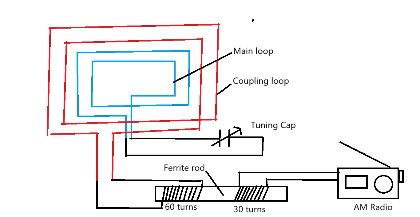
Signal improvement using a ferrite rod with a small loop antenna
I have used my small loop antenna (which has a main loop and a coupling loop that can be tuned using a variable capacitor) with an AM radio receiver to receive MW broadcasts. However, the small loop antenna which was made by me was not working properly but when I connected a ferrite rod loop (which has two windings on it---one with 60 turns and the other with 30), I saw a great improvement in radio reception. I connected the 60 turns loop with the main loop of the small loop antenna and the 30 turns loop with the AM radio.
The ferrite loop is not working as an antenna and when I turned it, I didn't get any difference in signal strength. However, when I turned the small loop antenna, I saw the change in signal.
So, I need to know why this has happened and did the ferrite rod work like a balun?
I have attached the diagram of the setup.
-
What is the radiation pattern of a center fed dipole on the ground?
What is the radiation pattern of a center fed dipole on the ground?
Let's say I have a 1/2 wave dipole and simply place it on the ground. No raising it. What happens?
My specific case is 40 m, CW, QRP, but I'm interested in other configurations as well.
We can assume fairly moist soil with grass over it, as common in temperate regions in the North East USA.
-
LTE (4G) - Which external/outdoor antenna type is the best?
I've seen several antenna types out there, but I can't know for sure which model is the best for external/outdoor LTE (4G) use.
I have to say that I don't understand anything about LTE (4G) antennas...
PARABOLIC (MIME is possible with two?)

LPDA(❓) (MIME is possible with two?)

LPDA (in XPOL) (MIME)

FLAT PANEL (XPOL) (MIME)

QUESTION: What is the best type for external/outdoor LTE (4G) use?
Thanks! 🤗
-
How to determine if filter is well matched?
Hello i'm in process of creating band pass filters for my ham radio. I calculated the filter for 80m band basing on this website:

And recreated it in reality:

Then I started measuring it with nanoVNA, and tuning the trimmers to get best frequency response:


As You can see, the frequency response is nearly as simulated, but I'm not sure about the impedance matching. Is this how the Smith chart should look like? Is this filter good or bad? I'm concerned about that, because the rosponse is not 50ohm in whole passband, but only on the sides of it. Also, is this How logmag of s11 should look like?
-
Testing a balun in isolation
Consider a microwave RF source going to an unbalanced coaxial cable, then using a 1:1 balun to feed a dipole/Yagi style antenna. How can I test this 1:1 balun in isolation, independent of the type of balun used?
The following diagram shows a proposed test mechanism:

Case 1: Measure the RF power outputted from the coaxial cable, suppose this is x dBm.
Case 2: Apply a balun to turn coaxial cable into 2 halves of a balanced line. Use the coaxial ground to create 2 short transmission lines and feed these into a combiner. If the balun is working as designed, summing the balanced line signals should cancel them out, and y dBm will be at the noise floor. Otherwise I should be able to measure how close to balanced the line is by comparing how low y dBm is relative to x dBm.
At microwave frequencies I expect I will need to use phase-matched cables (or at least the same length of cable for UHF and below) for the 2 paths following the balun.
Does this testing mechanism make sense? Is there a better way to test the function of a generic 1:1 balun?
-
After upgrading the firmware on my IC-7300, there's a new preset in a language I can't understand, what is it?
I recently upgraded the firmware on my Icom IC-7300 and a new menu item appeared: "Preset". I assume this is a way to save different radio configurations but I haven't looked into it yet. Inside "Preset" there were two items, FT8 which I'm familiar with and another written in a language I don't understand:

I guess it's Japanese, but I don't speak so I can't be sure. What does it say? What is it?
-
What is an expected IF level of SA612?
I tried to use SA612 as a frequency mixer. Since it's a Gilbert cell, it has a high input impedance. Thus I added a pair of transformers as "Experimental Methods in RF Design" book suggests:

The mixer seems to work:

Here I'm using 15 Mhz 12 dBm LO signal, RF is -16 dBm and I change it in 1-3 Mhz range to make sure that the mixer works as it supposed to. Two smaller signals on the left and on the right are IF, e.g. mixing products. 15 Mhz signal in the middle is a LO leakage. It's something you would expect to see in a mixer. LO can be lowered to 8 dBm, which causes 3 dB loss in mixing products.
(For the record, I also tried to use a simpler circuit without transformers. It kind of worked but the level of mixing products where MUCH lower.)
The result surprised me. I've been using diode ring mixers before and observed a much higher level of IF. For instance here I'm using a balanced diode ring mixer made of two FT50-43 ferrite cores and four 1N5818 Schottky diodes:

RF is the same -16 dBm, but LO is only -18 dBm. This mixer can be safely driven with 10-13 dBm which gives a much higher IF level.
This brings me to the question. Is an IF level which I got with SA612 an expected result or maybe I'm doing something wrong? Maybe you could suggest another test circuit?
-
What is the decimal in Morse Code?
The ITU's International Morse Code recommendation ITU-R M.1677-1 specifies a "Full stop (period)" as ".−.−.−", however it falls short of specifying a decimal point. Even the examples, though they illustrate fractional numbers, don't show decimal usage.
ITU's Phonetic Alphabet and Figures regulations (AP14), however, define a "Decimal point" and require it to be spoken as "DAY-SEE-MAL".
What then is the decimal in Morse code, and where is it defined?
-
Is it suitable to use DSSS in a narrow-band channel for a power-starved system
I want to build a system that can transmit data through 2-way radios as far as possible. I use the "line-in" as the input of the baseband signal in the transmitter and use the "audio out" as the output in the receiver. The RF modulation scheme seems to be a NBFM and the bandwidth of their audio input and output are about 2kHz-4kHz. The bit rate should be more than 64bits/s. I think there are many systems that work like this.
I was plan to use 64-MSK with RS code and interleaving at first but one of my workmate insist DSSS+BPSK without any coding. Personally, I don't think DSSS is a good choice in this situation.
I want to know who is right? Which one is better and why. Are there any mature schemes that I can choose?
Thanks.